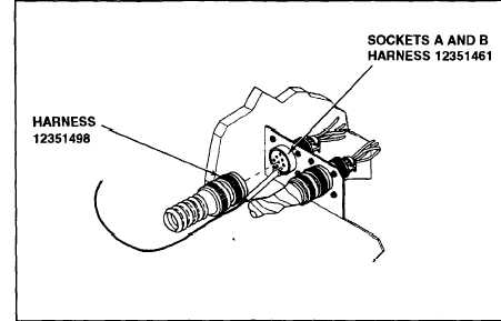
B Reconnect wire harness 12351498 to crew AFES T/A panel. Disconnect
wire harness from bracket-mounted socket 12351461 in driver’s compart-
ment. Place red lead of multimeter in pin socket A of bracket-mounted
socket 12351461 and ground black lead of multimeter. Check for 24 ± 3 vdc.
Place red lead of multirneter in pin socket B of bracket-mounted socket
12351461 and ground black lead of multimeter. Check for 24 ± 3 vdc. If
voltage is indicated in both circuits, replace wiring harness 12351498
(p 14-40.2). Verify problem is solved. If voltage is not indicated in both
circuits, connect wiring harness 12351498 to bracket mounted socket
12351461 and go to step C.
WARNING
Wire 10A, if functioning properly, is alive circuit carrying
a constant 24 volts. Exercise proper precautions when
working with this circuit. Failure to comply will result in
injury to personnel or equipment damage.
NOTE
Circuit breaker panel No. 2 is located directly behind
engine AFES T/A panel.
C
Disconnect wire harness 12351461 wire 10A from circuit breaker No. 6 on
circuit breaker panel No. 2. Place red lead of multimeter in circuit breaker
socket and ground black lead. Check for 24 ± 3 vdc. If voltage is indicated,
repair wire 10A or replace wiring harness 12351461 (p 14-40.2). Verify
problem is solved. If voltage is not indicated, replace circuit breaker No. 6
(p 6-54). Verify problem is solved.
2-306.11 Change 4
TM 9-2350-267-20