2-306.14
Change 4
TM 9-2350-267-20
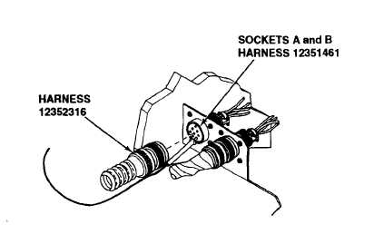
B. Disconnect wire harness from bracket-mounted socket 12351461 in driver’s
compartment. Place red lead of multimeter in pin socket A of bracket-
mounted socket 12351461 and ground black lead of multimeter. Check for
24 ± 3 vdc. Place red lead of multimeter in pin socket B of bracket-mounted
socket 12351461 and ground black lead of multimeter. Check for 24 ± 3 vdc.
If voltage is indicated in both circuits, replace wiring harness 12352316
(p 1440.2). Verify problem is solved. If voltage is not indicated in both
circuits, connect wiring harness 12352316 to bracket-mounted socket
12351461 and go to step C.
WARNING
Wire 10A if functioning properly, is a live circuit carrying
a constant 24 volts. Exercise proper precautions when
working with this circuit. Failure to comply will result in
injury to personnel or equipment damage.
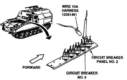
NOTE
Circuit breaker panel No. 2 is located directly behind
engine AFES T/A panel.
C Disconnect wire harness 12351461, wire 10A from circuit breaker No. 6 on
circuit breaker panel No. 2. Place red lead of multimeter in circuit breaker
socket and ground black lead. Check for 24± 3 vdc. If voltage is indicated,
repair wire 10A or replace wiring harness 12351461 (p 1440.2). Verify
problem is solved. If voltage is not indicated, replace circuit breaker No. 6
(p 6-54). Verify problem is solved.