HOOK UP STE/lCE TEST EQUIPMENT TO DCA (CONTINUED)
C
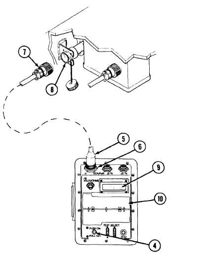
Install plug W1P1 (5) on VTM jack J1 (6).
D
Install plug W1P2 (7) to DCA connector (8) in driver’s
compartment.
E
Push VTM circuit breaker (4) to on.
1 If display (9) shows 8888, then - - - -, go to step F.
2 If display (9) is not blank but does not show 8888 and
- - - -
, writeup DA form 2404 on faulty VTM display. Report
problem to supervisor.
3 If display (9) is blank, refer to TM 9-4910-571-12&P for
troubleshooting of STE/ICE
F
Perform VTM confidence check. See operating instructions on
flip cards (10). If VTM confidence test does not pass, replace
STE/ICE
G
Proceed to appropriate STE/ICE test.
TA312639
2-48.3
Change 1
TM 9-2350-267-20