PROJECTILE RACK BASE, SUPPORTS AND VEHICLE WALL-MOUNTED RESTRAINTS REMOVAL AND INSTALLATION (CONTINUED)
INSTALLATION
NOTES
• Aline restraints, supports and adapter with scribe
marks for correcet positioning at installation.
• Apply zinc chromate paste (item 46, Appx D) between
all steel and aluninum mating surfaces.
l Ensure that shims are installed in props number and
location.
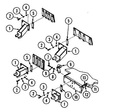
A Install rack base (30) on vehicle hull floor with 16 screws (31), 16 new
lockwashers (32), 16 flat washers (33), and 32 flat washers shims(34).
B
Install adapter (23) on vehicle floor with two screws (24), two new lockwashers
(25) and two flat washers (26) from the top; and two screws (27), two new
lockwashers (28), and two flat washers (29) from the end.
C Install right and left rear base supports (19) with two screws (20), two new
lockwashers (21) and two flat washers (2) for each support.
D lnstall right and left front base SUPPOrtS (17), shims (17A) and angles (18) on
vehicle floor with five screws (14), five new lockwashers (5) and five flat
washers (16) for each support.
NOTE
Install correct restraints in marked positions. Install
correct number of shims between each restraint and
bulkhead mounting area.
E
Install bracket (10) on forward bulkhead with four screws (11), four new
lockwashers (12) and four flat washers (13).
F
Install air cleaner indicator and bracket assembly (6) with screw (7), flat
washer (8) and new lockwasher (9).
G Install four rear rack restraints (1) and shims (5) on vehicle wall with four
screws (2), four new lockwashers (3) and four flat washers (4) for each.
11-4.1/11-4.2 blank)
Change 4
TM 9-2350-267-20