TM 9-2350-261-34
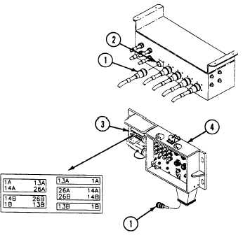
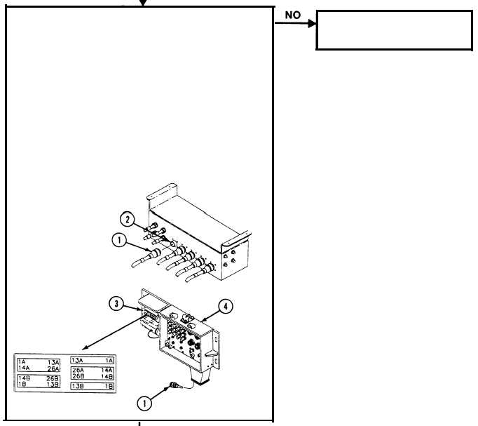
1. Remove cable W118, plug P105 (1) from PATCH
PANEL BOX A10, jack J135 (2).
N O T E
Use diagram.
2. Measure resistance between pins on cable W118, plug
P105 (1) and pins on connector J101 (3) of EXTERNAL
COMMUNICATION BOX A11 (4) as follows:
Pin 1 to Pin 1A
Pin 7 to Pin 4A
Pin 2 to Pin 1B
Pin 8 to Pin 4B
Pin 3 to Pin 2A
Pin 9 to Pin 5A
Pin 4 to Pin 2B
Pin 10 to Pin 5B
Pin 5 to Pin 3A
Pin 11 to Pin 6A
Pin 6 to Pin 3B
Pin 12 to Pin 6B
(Con’t on next page)
1. Replace cable W118
(page 6-130).
2. Verify no faults found.
2.1-40
Change 3