TM 9-2350-261-34
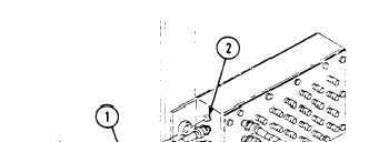
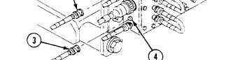
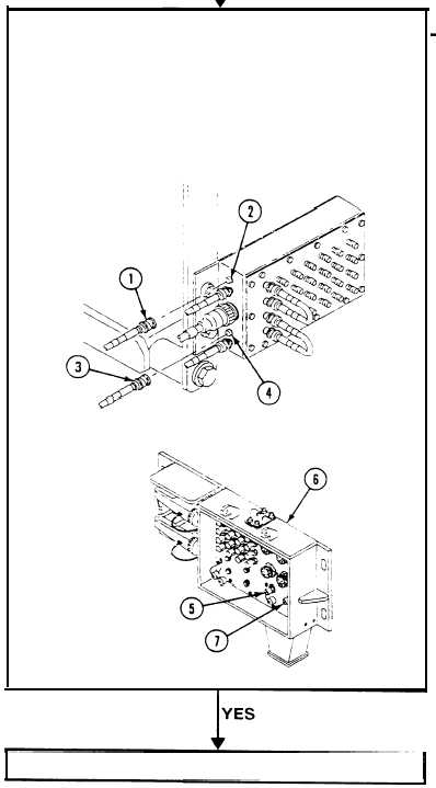
1. Remove cable W101, plug P1 (1), from jack J1 (2) and
cable W102, plug P2 (3) from jack J4 (4) of CURBSIDE
DATA PANEL ASSEMBLY A12.
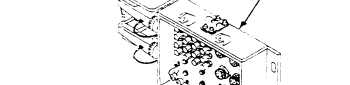
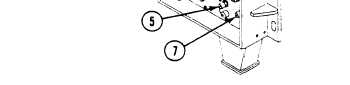
2. Measure resistance between pin on plug P1 of cable
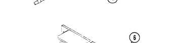
W101 (1) and jack J103 LAN A (5) of EXTERNAL
COMMUNICATION BOX A11 (6) front panel. Repeat
check for cable W102, plug P2 (3) and jack J104 LAN
B (7)
3. Does multimeter read 0 ohms for each measurement?
1. Verify no faults found.
1. Replace cable W101 and/or
cable W102 (page 6-124).
2. Verify no faults found.
2.1-38
Change 3