TM 9-2350-261-34
1.
2.
3.
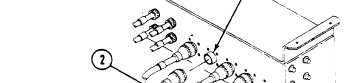
Remove cable W115, plug P106 (1) from PATCH
PANEL BOX A10, jack J136 (2).
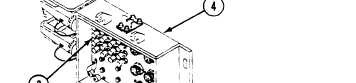
Measure resistance between pins of cable W115, plug
P106 (1) and posts on front panel (3) of EXTERNAL
COMMUNICATION BOX A11 (4) as follows:
Post 1 (Bot) to pin A
Post 5 (Bot) to pin J
Post 1 (Top) to pin B
Post 5 (Top) to pin K
Post 2 (Bot) to pin C
Post 6 (Bot) to pin L
Post 2 (Top) to pin D
Post 6 (Top) to pin M
Post 3 (Bot) to pin E
Post 7 (Bot) to pin N
Post 3 (Top) to pin F
Post 7 (Top) to pin P
Post 4 (Bot) to pin G
Post 8 (Bot) to pin R
Post 4 (Top) to pin H
Post 8 (Top) to pin S
Does multimeter read 0 ohms for each measurement?
1. Verify no faults found.
1. Replace cable W115
(page 6-128).
2. Verify no faults found.
Change 3
2.1-37