TM 9-2350-261-34
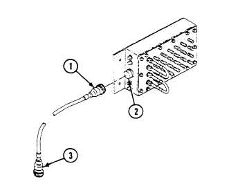
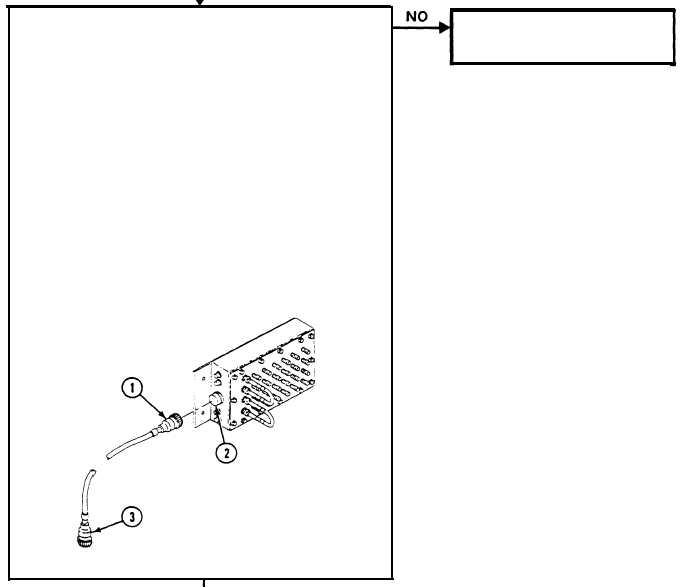
1. Remove cable W124, plug P1 (1) from CURBSIDE
DATA PANEL jack J3 (2).
2. Measure resistance between sockets on plug P1 (1) and
pins on plug P109 (3) of cable W 124 as follows:
Socket A to pin A
Socket N to pin N
Socket B to pin B
Socket P to pin P
Socket C to pin C
Socket R to pin R
Socket D to pin D Socket S to pin S
Socket E to pin E
Socket T to pin T
Socket F to pin F
Socket U to pin U
Socket G to pin G Socket V to pin V
Socket H to pin H
Socket W to pin W
Socket J to pin J
Socket X to pin X
Socket K to pin K Socket Y to pin Y
Socket L to pin L Socket Z to pin Z
Socket M to pin M Socket a to pin a
3. Does multimeter read 0 ohms for each measurement?
1. Verify no faults found.
1. Replace cable W124
(see your -20).
2. Verify no faults found.
2.1-26
Change 3


