TM 9-2350-261-34
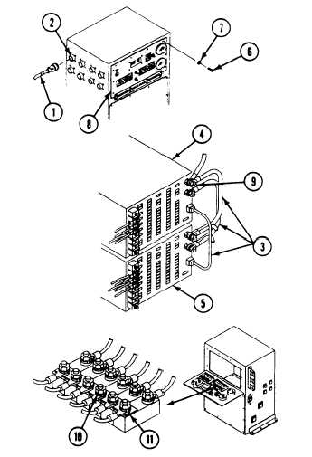
1. Disconnect Fabricated Tool (1) from external AC power
and from J24 (2) on POWER CONTROL
ENCLOSURE.
2. Install all circuits (3) on power supplies PSI (4) and
PS2 (5).
3. Remove ten screws (6) and lockwashers (7) and lower
faceplate (8) of Power Control Enclosure. Discard
lockwashers.
4. Measure resistance between PSI (+) OUTPUT ter-
minal (9) and DC bus bar at terminal 1 (10) of circuit
breaker CB15 (11).
5. Does multimeter read 0 ohms?
1. Replace circuit 31E
(page 6-118).
2. Verify no faults found.
2.1-14
Change 3


