TM 9-2350-261-34
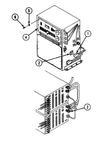
1. Remove cable W4, plug P1 (1) from Power Control
Enclosure, jack J25 (2).
2. Measure resistance between power supply PS2 (-)
OUTPUT terminal (3) and jack J25 (2) outer sleeve.
3. Does multimeter read 0 ohms?
1. Install cable W4, plug P1 (1), on Power Control
Enclosure, jack J25 (2).
2. Raise faceplate (4) and secure to Power Control Enclo-
sure with ten new lockwashers (5) and screws (6).
3. Verify no faults found.
1. Replace circuit 32E
(page 6-118).
2. Install cable W4, plug P1 (1),
on Power Control Enclosure,
jack J25 (2).
3. Raise faceplate (4) and se-
cure to Power Control Enclo-
sure with ten new
lockwashers (5) and
screws(6).
4. Verify no faults found.
2.1-16
Change 3


