TM 9-2350-261-34
11.
12.
13.
14.
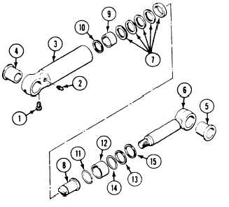
Remove bleeder valve (1) and lube fitting (2)
from cylinder (3).
If damaged or worn, press sleeve bushing
(4) from cylinder (3).
If damaged or worn, press sleeve bushing
(5) from piston rod (6).
Discard sleeve bushings (4 and 5).
CLEAN, INSPECT, AND REPAIR
15.
16.
17.
Check threads of plunger and piston. Chase
damaged threads with a die. Replace parts
as a matched set if the threads of either
part are stripped or worn.
Check parts shown in figure on next page
that have reference letters.
Check the parts dimensions with chart on
next page to determine replacement.
A S S E M B L E
18.
19.
If removed, press new sleeve bushing (4) in
cylinder (3) from side opposite lube fitting
(2). Use arbor press.
If removed, press new sleeve bushing (5)
into piston rod (6). Use arbor press.
N O T E
Install new packings (7) with sealing lips
facing away from flange on piston (8).
Lips face toward inside of cylinder (3).
20. Install five new packings (7), new bearing
(9), and new retaining ring (10) on piston
assembly (8).
21.
22.
23.
24.
Apply a light coat of lubricating oil to piston
assembly (8) and to inside of cylinder (3).
Install piston assembly (8) in cylinder (3).
Install new retaining ring (11 ) in cylinder
(3). Make sure it seats in groove.
Apply a light coat of lubricating oil to new
bearing (12).
Install new bearing (12) in cylinder (3).
NOTE
Install new wiper ring (13) with grooved
edge facing out of cylinder toward retain-
ing ring.
26.
27.
28.
29.
Install new packing (14), new wiper ring
(13), and new retaining ring (15) in cylin-
der (3).
Apply a light coat of lubricating oil to piston
rod (6).
Install piston rod (6) in cylinder (3). Main-
tain inward pressure on piston rod and ro-
tate clockwise until secure.
Install bleeder valve (1) and lube fitting (2)
in cylinder (3).
7-10
ml:
/u If I-1111 -llr 4-4rllrl
2
5 .