TM9-2350-261-34
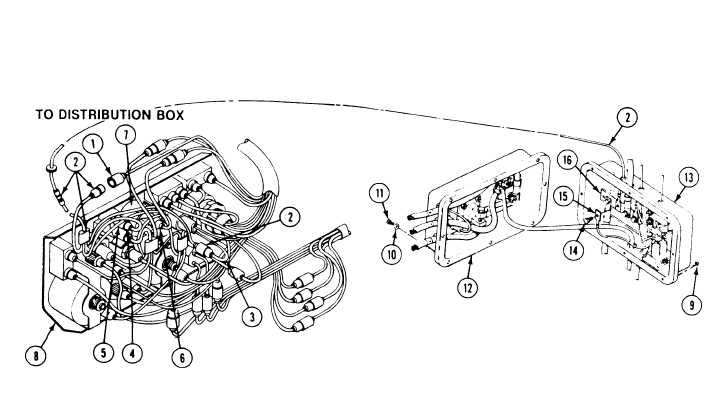
4. Disconnect circuit 15 lead (1) from instrument
panel wiring harness (2).
5. Disconnect circuit 14 lead (3) from panel
wiring harness (2),
6. Disconnect circuit 10 lead (4) from panel
circuit breaker (5).
7. Disconnect circuit 27E lead (6) from battery
generator gage (7).
8. Remove panel wiring harness (2) from
instrument panel (8).
9. Remove eight locknuts (9), washers (10),
and screws (11). Separate master switch
panel (12) from distribution box (13).
Discard locknuts.
10. Remove screw (14), circuit 450 lead (15),
and harness lead (2) from bus bar (16).
11. Remove panel wiring harness (2) from
distribution box ( 13).
I N S T A L L
12. Install harness lead (2) through hole in top
of distribution box ( 13). Secure harness lead
and circuit 450 lead (15) to bus bar (16)
with screw (14).
13. Install master switch panel (12) on
distribution box (13). Secure with eight
screws (11), washers (10), and new
locknuts (9).
14. Connect circuit 27E lead (6) to battery
generator gage (7).
15. Connect circuit 10 lead (4) to instrument
panel circuit breaker (5).
16. Connect circuit 14 lead (3) to instrument
panel wiring harness (2).
17. Connect circuit 15 lead (1) to panel wiring
harness (2).
GO TO NEXT PAGE
6-7