page 40.1-5
TM 9-2350-261-20-1
N O D A T A O U T P U T F R O M D A T A P A N E L A 1 3
I N I T I A L S E T U P
Tools:
Electronic Equipment Tool Kit
(Item 75.1, App D)
Digital Multimeter (Item 43, App D)
Personnel Required:
Signal Support System Specialist 31U10
Helper (H)
References:
See your -10
TM11-7010-256-12&P
See M1068 Wiring Diagram
(FO-9 thru FO-11)
Equipment Conditions:
Engine stopped/shutdown (see your -10)
Carrier blocked (see your –10)
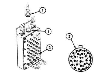
1. Remove cable W 126 plug P1 (1) from Data Panel A13
jack J3 (2).
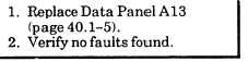
2. Measure resistance between posts (3) and pins of jack
J3 (2) as follows:
Post 1 (Red) to pin A
Post 7 (Red) to pin N
Post 1 (Blk) to pin B
Post 7 (Blk) to pin P
Post 2 (Red) to pin C
Post 8 (Red) to pin R
Post 2 (Blk) to pin D
Post 8 (Blk) to pin S
Post 3 (Red) to pin E
Post 9 (Red) to pin T
Post 3 (Blk) to pin F
Post 9 (Blk) to pin U
Post 4 (Red) to pin G
Post 10 (Red) to pin V
Post 4 (Blk) to pin H
Post 10 (Blk) to pin W
Post 5 (Red) to pin J
Post 11 (Red) to pin X
Post 5 (Blk) to pin K
Post 11 (Blk) to pin Y
Post 6 (Red) to pin L
Post 12 (Red) to pin Z
Post 6 (Blk) to pin M
Post 12 (Blk) to pin a
3. Does multimeter read 0 ohms for each measurement?
3-226.126
Change 3