TM 9-2350-261-20-1
1.
2.
3.
4.
Set MASTER SWITCH to ON (see your -10).
Set all DC CIRCUITS circuit breakers on Power Con-
trol Enclosure panel to ON.
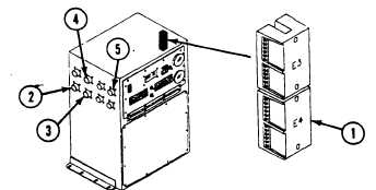
Measure voltage between terminal block E4 (1) and the
following jacks on Power Control Enclosure:
J33 (2) socket A
J34 (3) socket A
J35 (4) socket A
J36 (5) socket A
Does multimeter read 22 volts DC or more for all
readings?
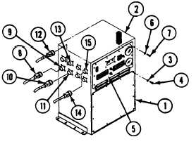
1. Install cover (1) on Power Control Enclosure (2) and
secure with twelve new lockwashers (3) and screws (4).
2. Raise faceplate (5) and secure to Power Control Enclo-
sure (2) with ten new lockwashers (6) and screws (7).
3. Install the following cable plugs:
W45 plug P13 (8) on jack J33 (9)
W10 plug P14 (10) on jack J34 (11)
W9 plug P15 (12) on jack J35 (13)
W32 plug P16 (14) on jack J36 (15)
4. Verify no faults found.
1. Go to: Power Enclosure A1
DC Input/Output Inopera-
tive (page 3-226.1).
3-226.96
Change 3