TM 9-2350-247-34
REPLACE DIODE AND MOTOR RESISTOR — Continued
0071 00
NOTE
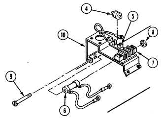
Note direction of arrow on diode so it can be installed later.
2. Remove diode (4) from holder (5).
3. Remove motor resistor (6) leads from terminals No. 4 and No. 6 on terminal board (7).
4. Remove nut (8), screw (9), and motor resistor (6) from bracket (10).
INSPECTION-ACCEPTANCE AND REJECTION CRITERIA
1. Use multimeter to check diode. Set meter to above 200 ohm scale. Place probes on each end of diode. Switch probes
and note reading. Multimeter must indicate continuity in one position and high resistance in the other for diode to
operate properly.
2. Check resistance of motor resistor. Multimeter should read 0 ohms resistance. Replace resistor if reading is infinity.
0071 00-2