TM 9-2350-247-20-3
REPLACE/REPAIR HEATER CONTROL BOX — Continued
0472 00
NOTE
Start switch has locked position and spring-loaded position.
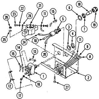
3.
Install start switch in heater control box as follows:
a.
Place start switch (1) with locked position at top of heater control box (2).
b.
Install start switch (1) in heater control box (2) with washer (3) and nut (4).
c.
Install cable assembly (5) in heater control box (2) with lock washer (6) and nut (7).
d.
Place lead 20 (8), lead 19 (9), lead 19-2 (10), lead 14 (11), jumper 21-18 (12), jumper 21-14 (13), lead 13-19 (14),
and jumper 15-17 (15) on start switch (1). Secure with six lock washers (16) and screws (17).
NOTE
Ensure that both circuit breaker screws are tight.
4.
Install indicator light in heater control box as follows:
a.
Install bulb (18) in cable assembly (5) with cap (19).
b.
Install lead 19-2 (10) on start switch (1) with lock washer (16) and screw (17).
c.
Install lead 17-3 (20) on circuit breaker (21) with lock washer (22) and screw (23).
d.
Install indicator light negative lead (24) on circuit breaker (21) with lock washer (25) and nut (26).
5.
Install circuit breaker in heater control box as follows:
a.
Install circuit breaker (21) in heater control box (2) with four new lock washers (25), screws (27), indicator light
negative lead (24), and two nuts (26).
0472 00-6