TM 9-2350-247-20-3
REPLACE/REPAIR HEATER CONTROL BOX — Continued
0472 00
ASSEMBLY
NOTE
Before connecting electrical leads, check connection diagram (1) to make sure of proper
connection.
Make sure key in outlet receptacle is at the top.
1.
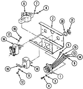
Install outlet receptacle in heater control box as follows:
a.
Install outlet receptacle (1) in heater control box (2). Secure with four new lock washers (3) and screws (4).
b.
Install lead 17 (5) on circuit breaker (6) with lock washer (7) and screw (8).
c.
Install lead 12B (9) on heater switch (10) with lock washer (11) and screw (12).
d.
Install lead 19 (13), lead 20 (14), and lead 14 (15) on start switch (16) with three new lock washers (17) and
screws (18).
NOTE
Heater switch is marked ON and OFF.
2.
Install HI-LO heater switch in heater control box as follows:
a.
Place heater switch (10) with ON at the top of heater control box (2).
b.
Install lead 13-19 (19) and lead 12B (9) on heater switch (10) with lock washer (11) and screw (12).
c.
Install heater switch (10) in heater control box (2) with instruction plate (if applicable), new lock washer (20), and
nut (21).
0472 00-5


