7-22
Change 1
TM 9-2350-267-20
I
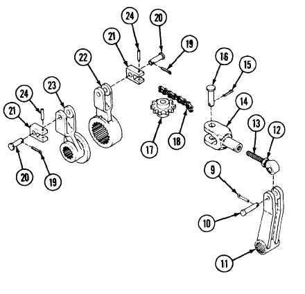
LINKAGE IN POWERPACK COMPARTMENT: REMOVAL, DISASSEMBLY, ASSEMBLY, INSTALLATION AND ADJUSTMENT
(CONTINUED)
c
Unscrew and remove rod (13) from clevis (14).
D
Remove cotter pin (15) and discard.
E
Remove pin (16) and sprocket (17) with chain (18) from clevis
(14).
F
Remove two cotter pins (19), two pins (20) and two clevises (21)
.
with chain (18) from right brake lever (22) and left brake lever
(23). Discard cotter pins.
G
Remove two pins (24) and separate chain (18) from clevises (21).
Discard pins.
ASSEMBLY
A
Install two clevises (21) on ends of chain (18) with two new pins
(24).
B Position chain (18) with clevises (21) on sprocket (17).
c
Install clevises (21) in right brake lever (22) and left brake lever
(23) with two pins (20) and two new cotter pins (19).
D Install clevis (14) on sprocket (17) with pin (16) and new cotter
pin (15).
DISASSEMBLY
E
Screw rod end (13) into clevis (14) and tighten nut (12).
A
Remove cotter pin (9) and pin (10) from lever (11). Discard cot-
F
Install lever (11) on rod end (13) with pin (10) and new cotter
ter pin.
pin (9).
B Loosen nut (12) on rod end (13).
TA312845