|
| |
TM 9-2350-287-34
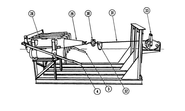
9-4. PROJECTILE RACK SECTION REPAIR (continued).
WARNING
Projectile, cable, and connecting hardware under tension may snap out of position.
Monitor force gage from a safe distance. SAFETY GOGGLES must be worn during
test. Failure to heed this warning can result in Injury or death.
NOTE
Slippage may occur before full load is applied and will stop when rotating band contacts
locking shoe.
6.
Turn winch (33) and applied tension to projectile (29)
NOTE
• Projectile rack passes test if 400 Ibs. of tension can be applied and rotating band does not
pass under locking shoe.
• If it does not pass test, repair projectile rack assembly.
7.
Remove force gage (30) from projectile (29).
8.
Remove quick release pin (32) and force gage (30) from cable.
9.
Raise both locking handles (3 and 4) and remove projectile (29) from tube (28).
9-21
|