Order this information in Print

Order this information on CD-ROM

Download in PDF Format


Click here to make tpub.com your Home Page

Page Title: STEERING CONTROL LINKAGE REPLACEMENT (continued)
Back | Up | Next

Click here for a printable version

Google


Web
www.tpub.com

Home


Information Categories
.... Administration
Advancement
Aerographer
Automotive
Aviation
Combat
Construction
Diving
Draftsman
Engineering
Electronics
Food and Cooking
Math
Medical
Music
Nuclear Fundamentals
Photography
Religion
USMC
   
Products
  Educational CD-ROM's
Printed Manuals
Downloadable Books


TM   9-2350-287-20-2 12-2. STEERING CONTROL LINKAGE REPLACEMENT (continued). 10. 11. 12. 13. 14. WARNING 15. 16. 
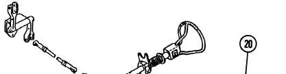
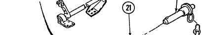
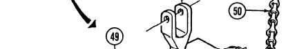
Secure  quick-release  pin  (20)  and chain  (50)  to  lever  (21)  with  safety wire  (49). Spring   located   “within   steering shaft  assembly  is  under  tension and  may  snap  out  of  position when  spring  pin  is  installed.  To avoid  injury  to  personnel,  use care   during   installation. 
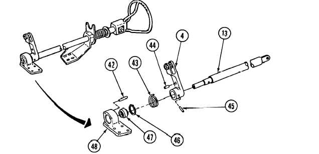
Install new spring pin (44) and spring (43) on lever (4). Install  lever  (4)  and  new  spring  pin (45) on shaft (13). 
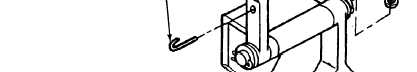
Install bearing (47), new retaining ring (46),  and  new  spring  pin  (42)  on bracket  (48). Install shaft (13) on bracket (48). Install  bracket  (36)  on  shaft  (13)  with  bearing  (37)  and  two  new  retaining  rings  (41). Install master warning light bracket (38) on bracket (36) with three screws (39) and new lockwashers (40). 12-8

Privacy Statement - Press Release - Copyright Information. - Contact Us - Support Integrated Publishing

Integrated Publishing, Inc. - A (SDVOSB) Service Disabled Veteran Owned Small Business