|
| |
TM 9-2350-287-20-2
11-13. TRACK SHOE REPLACEMENT (continued).
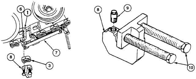
5.
Install end connector puller (8) through bolt hole in end connector (3). End connector puller (8) must rest flat on
end connector (3), and straight pin (9) must engage bolt hole on both sides of end connector (3) so bolts (10) of
end connector puller (8) engage two track link pins (6). Tighten or loosen straight pin (9) until end connector
puller (8) is properly adjusted.
CAUTION
· Tighten bolts on end connector puller evenly, so end connector is pulled evenly
off track link pins. Failure to do this can lead to damage to puller and track link
pins.
· When tapping end connector puller with hammer, strike bolts squarely to avoid
mushrooming the heads of bolts and damaging puller.
NOTE
To help loosen end connectors, tap bolts of end connector puller with hammer
while moving or removing end connectors.
6.
Using end connector puller (8), tighten two bolts (10) and move two end connectors (3) about one inch away from
track shoe (1). If bolts (10) on end connector puller (8) bind, tap end connector puller (8) with hammer.
7.
Install track connecting fixture (7) on two track link pins (6).
8.
Using end connector puller (8), tighten two bolts (10) and remove two end connectors (3) from four track link pins
(6). If end connectors (3) become cocked during removal, remove end connector puller (8) and tap end connector
(3) with hammer until end connector (3) is straight on track link pins (6). Reinstall end connector puller (8), and
continue to remove two end connectors (3).
9.
Repeat steps 5 through 8 on two end connectors (3) on inside of track.
WARNING
Release tension on track connecting fixtures evenly. Track is under tension and
can move suddenly, causing severe injury to personnel.
10.
Remove two track connecting fixtures (7) and track shoe (1) from ends of track.
Change 1 11-29
|