|
| |
TM 9-2350-287-20-2
15-63. COMMANDER’S SEAT REPAIR (continued).
12.
13.
14.
15.
16.
17.
18.
19.
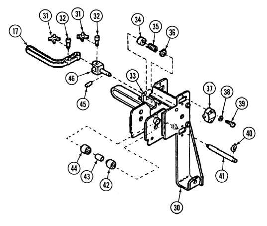
Insert pin assembly (46) in hole in pin housing (33).
Place sleeve (34), spring (35), and washer (36) in pin housing (33). Install pin assembly (46) and secure with
grooved pin (45).
Lightly coat locking handle (17) with grease.
Install locking handle (17) on pin assembly (46) with two headed pins (32) and new washers (31).
Lightly coat four roller assemblies (37) with grease.
Install four roller assemblies (37) on manual control lever (30) with two screws (39) and new Iockwashers (38)
each.
Install four bearings (42 and 44) on manual control lever (30), separated by two spacers (43), on two shafts
(41).
Secure two shafts (41 ) in manual control lever (30) with four washers (40).
15-162
|