TM 9-2360-287-20-1
2-19. TROUBLESHOOTING CHART (continued).
u. AUXILIARY POWER UNIT (continued).
(6) GENERATOR CHARGING SYSTEM INDICATOR
READS IN LOW YELLOW OR RED WITH MAIN
ENGINE CHARGING (continued).
Repair wire 61B or replace APU
controller box (para 7-22). Verify
problem is solved.
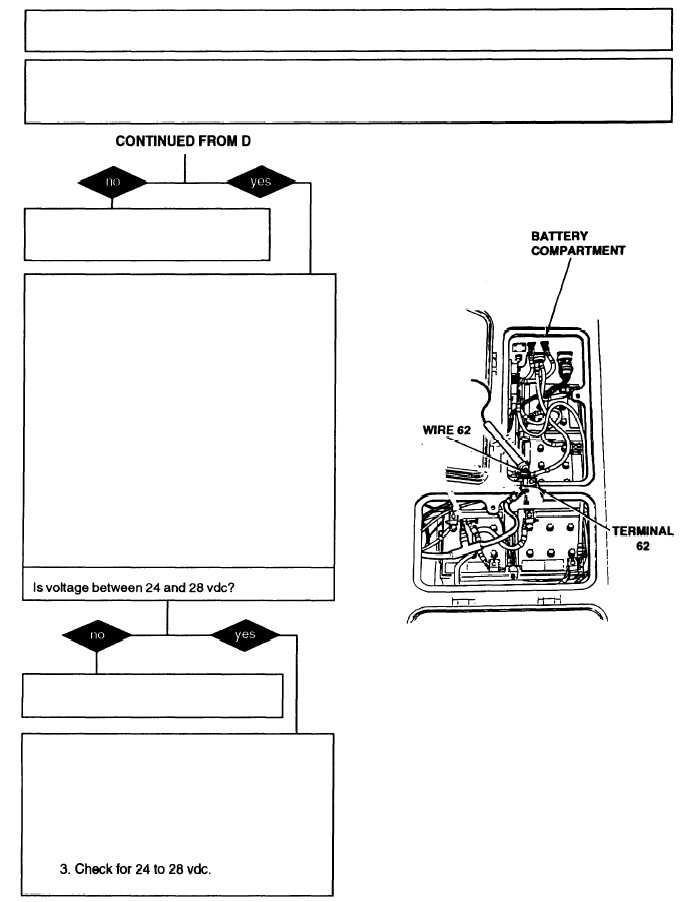
E. 1. Assemble and install APU control box
(para 7-22).
2. Connect harness 12330248 to APU volt-
age regulator.
3. Operate APU with APU Generator switch
ON (refer to TM 9-2350-287-10).
4. Place red probe of multimeter on terminal
62 at battery compartment and black probe
to ground.
5. Check for 24 to 28 vdc.
6. Turn APU OFF (refer to TM 9-2350-287-
10).
Replace APU voltage regulator (para 7-15).
Verify problem is solved.
F. 1. Operate APU with APU GENerator
switch ON (refer to TM 9-2350-287-10).
2. Place red probe of multimeter on terminal
B of APU starter/generator and black probe
to ground.
Continued on next page
2-319