TM 9-2350-287-20-1
2-19. TROUBLESHOOTING CHART (continued).
u. AUXILIARY POWER UNIT (continued).
(5) ENGINE OVERHEATS.
Initial Setup:
Tools/Test Equipment:
l Digital multimeter (DMM) (Item 13, Appendix 1)
l General mechanic’s tool kit (Item 24,
Appendix 1)
Personnel Required: Two
Equipment Conditions:
l APU side door opened (refer to
TM 9-2350-287-10).
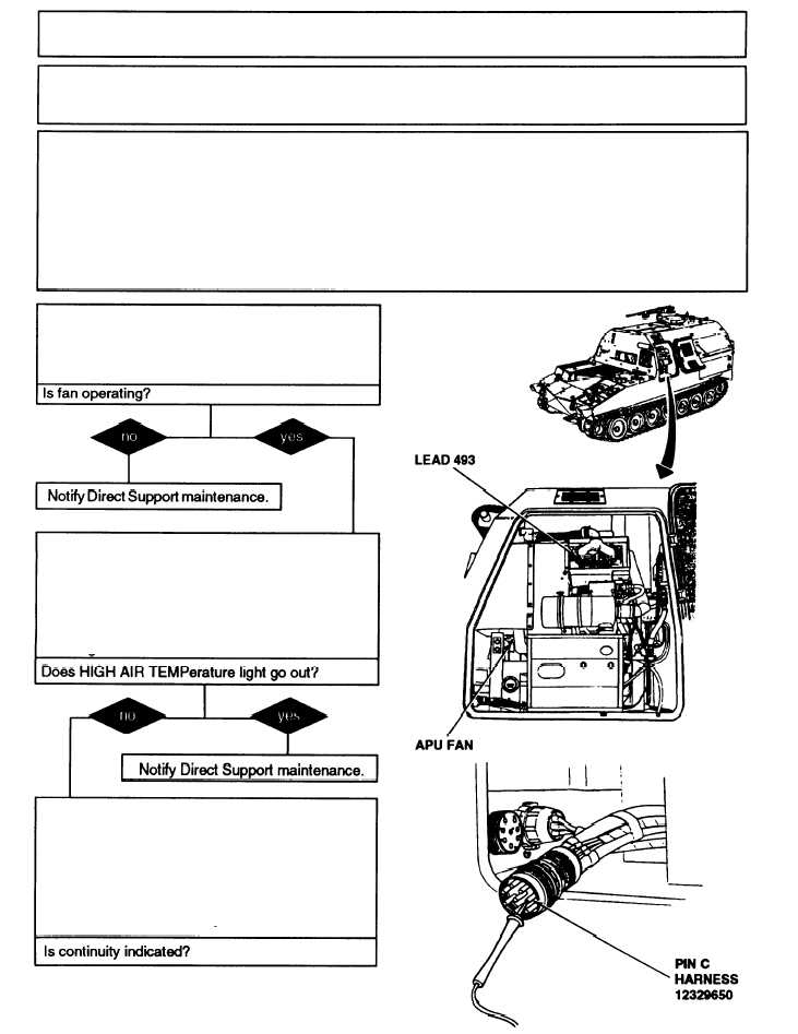
A. 1. Start the APU (refer to TM 9-2350-287-10).
2. While APU is running, make sure APU fan is
rotating.
B. 1. Shut down the APU (refer to TM 9-2350-
287-10).
2. If HIGH AIR Temperature light is on after
APU engine has cooled, disconnect lead 493
from high air temperature switch on APU
engine.
C. Disconnect harness 12329650 connector at
APU compartment wall.
2. Using multimeter, check for continuity
between lead 493 and pin C of connector.
3. Check for continuity
2-314
Continued on next page