TM 9-2350-287-20-1
2-19. TROUBLESHOOTING CHART (continued).
u. AUXILIARY POWER UNIT (continued).
(2) ENGINE FAILS TO CRANK. All other electrical
systems operate (continued).
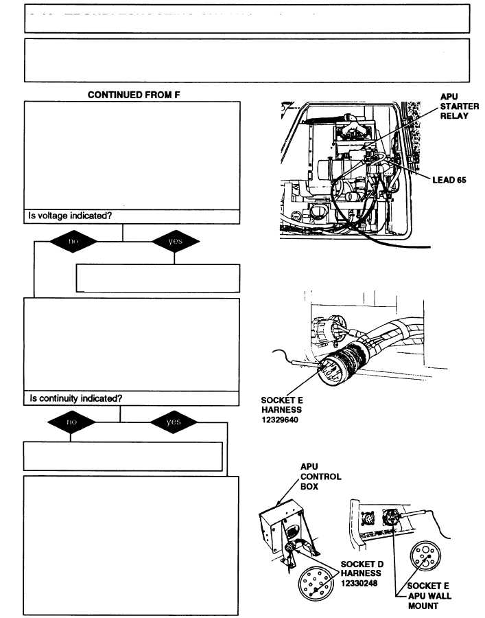
F.
6. With the aid of an assistant turn MASTER
switch ON and hold APU PREHEAT AND
START switch (refer to TM 9-2350-287-10).
7. Check for 24 ± 3 vdc.
8. Release APU PREHEAT AND START
switch and turn MASTER switch OFF (refer to
TM 9-2350-287-10).
Replace starter relay (para 18-18).
Verify problem is solved.
G. 1. Disconnect harness 12329640 from APU
compartment wall connector.
2. Place multimeter red probe in lead 65 and
black probe on pin E of harness 12329640
connector.
3. Check for continuity.
Repair wire 65 or replace harness 12329640
(para 18-21). Verify problem is solved.
H.
1. Connect lead 65 to onput side of APU
starter relay.
2. Disconnect harness 12330248 from APU
control box.
3. Place multimeter red probe in socket E of
harness 12330248 APU wall mount connec-
tor and black probe in socket D of harness
12330248 APU control box connector.
4. Check for continuity.
Continued on next page
2-306