TM 8-2350-287-20-1
I
2-19. TROUBLESHOOTING CHART (continued).
I
t.
HYDRAULIC SYSTEMS, ELECTRICAL (continued).
(2) CONVEYOR CHAIN WILL NOT OPERATE IN
EITHER DIRECTION .
Initial Setup:
Tools/Test Equipment:
Equipment Conditions:
l Digital multimeter (DMM) (Item 13, Appendix 1)
• MASTER switch set to OFF (refer to TM
l General mechanic’s tool kit (Item 24,
9-2350-287-10).
Appendix 1)
l Conveyor deployed (refer to TM 9-2350-287-10).
NOTE
l Instead of using multi meter
for voltage check, STE/lCE
troubleshooting,
INDIVIDUAL
BATTERY VOLTAGE TEST-TEST
89 maybe performed.
l Instead of using multi meter
for continuity check, STE/lCE
troubleshooting, TEST 91 may
be performed.
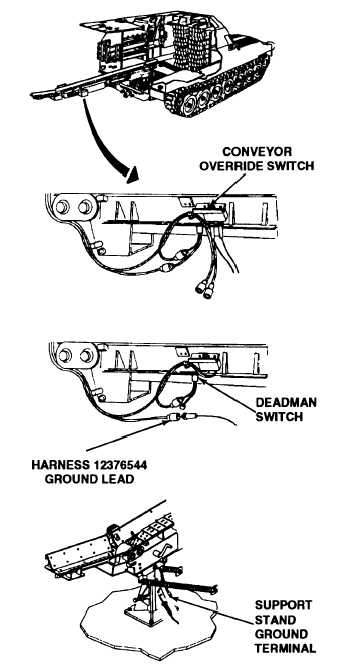
A. 1. Disconnect ground leads from conveyor
override switch.
2. Place red lead of multimeter on one ground
connector of switch and place black lead on
the other.
3. Turn conveyor override switch ON (refer to
TM 9-2350-287-10).
4. Check for continuity.
Is continuity indicated?
I
Replace conveyor override switch (para
7-24). Verify problem is solved.
B. 1. Reconnect ground leads to conveyor over-
ride switch.
2. Disconnect conveyor harness 12376544
ground Ieads from conveyor deadman switch.
3. Place one lead of multimeter in ground
socket of harness 12376544 and place other
lead at ground terminal on the conveyor sup-
port stand.
Continued on next page
2-286