TM 9-2350-287-20-1
I
2-19. TROUBLESHOOTING CHART (continued).
CONTINUED FROM C
Notify Direct Support maintenance.
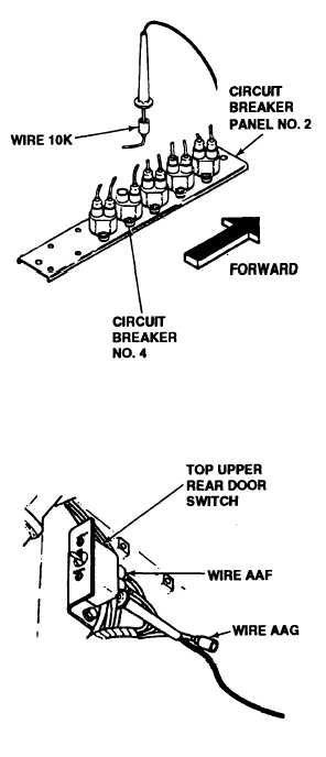
D. 1. Reconnect wire 10 of harness 12330252
to circuit breaker no. 4
2. Disconnect wire 10K from circuit breaker
no. 4 of panel no. 2.
3. Place multimeter red lead in wire 10K and
ground black lead.
4. Turn MASTER switch ON (refer to TM 9-
2350-287-10).
5. Check for 24 ± 3 VdC.
6. Turn MASTER switch OFF (refer to TM 9-
2350-287-10).
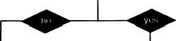
Was voltage indicated?
I
Replace circuit breaker no. 4 of circuit breaker
panel no. 2 (para 7-11). Verify problem is
solved.
Repair wire 10K or replace harness
12376405 (para 7-57). Verify problem is
solved.
CONTINUED FROM STEP B
E. 1. Reconnect wire 10 to upper rear door switch.
2. Disconnect wires AAF and AAG from upper
rear door switch.
Continued on next page
2-283