TM 9-2350-287-20-1
2-19. TROUBLESHOOTING CHART (continued).
h. LIGHTS (continued).
(13) TAILLIGHTS FAIL TO OPERATE. All other lights
operate (continued).
CONTINUED FROM A
B. 1. Install bulb and cover on taillight assem-
bly, and tighten six screws.
2. Remove eight screws, Iockwashers, and
brace from left side crew compartment.
3. Remove screws, spacers, and wiring har-
ness cover from rear wall of crew compart-
ment.
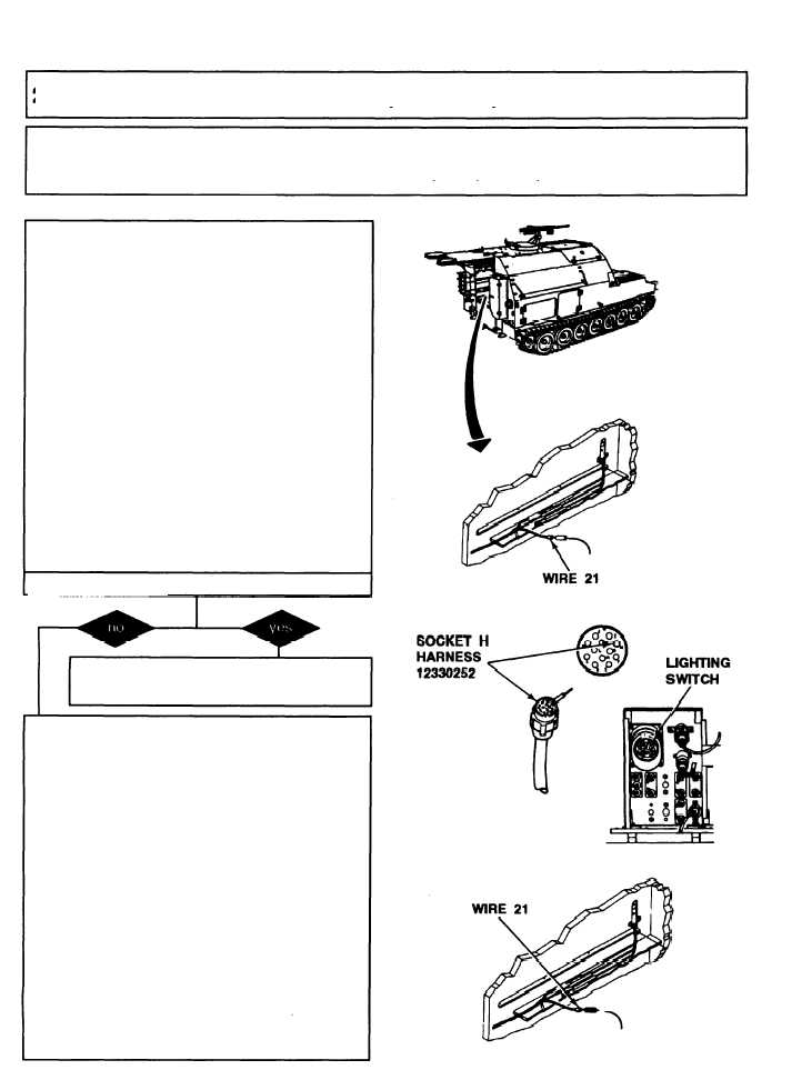
4. Disconnect wire 21 of harness 12330252
from taillight assembly harness.
5 Have assistant turn MASTER switch ON
(refer to TM 9-2350-287-10).
6. Check for 24 ± 3 wk.
7. Have assistant turn MASTER switch OFF
(refer to TM 9-2350-287-10).
Is voltage indicated?
Repair or replace Ieft taillight assembly (para
7-33). Verify problem is solved.
C. 1. Remove six screws and cover from
driver’s instrument panel.
2. Disconnect harness 12330252 from light-
ing switch.
NOTE
To complete this step you will need to fabri-
cate a multimeter extension using at least
12 feet of wire and make sure the end of the
wire is able to be used as a probe into a
socket.
3. Have assistant place one lead of muitim-
eter to socket H of harness 12330252 light-
ing switch connector and place other lead
on socket of wire 21 of harness 12330252
connector at rear of crew compartment.
4. Check for continuity.
Continued on next page
2-182


