TM 9-2350-287-20-1
2-19. TROUBLESHOOTING CHART (continued).
h. LIGHTS (continued).
(6) MASTER SWITCH INDICATOR LIGHT FAILS TO
OPERATE WITH MASTER SWITCH ON. All other
electrical systems operate.
Initial Setup:
Tools/Test Equipment:
Equipment Conditions:
Digital multimeter (DMM) (Item 13, Appendix I)
MASTER switch set to OFF (refer to TM
General mechanic’s tool kit (Item 24,
9-2350-287-10).
Appendix I)
NOTE
Instead of using multimeter
for voltage
check, STE/lCE
troubleshooting,
INDIVIDUAL
BATTERY VOLTAGE TEST-TEST
89 maybe performed.
Instead of using multi meter
for continuity check, STE/lCE
troubleshooting, TEST 91 may
be performed.
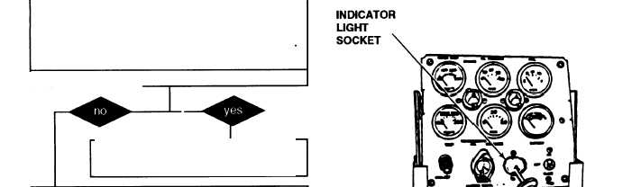
A. 1. Remove lens and light bulb from MASTER
switch indicator lamp socket.
2. Place red lead of multimeter in indicator
light socket and ground black lead.
3. Turn MASTER switch ON (refer to TM 9-
2350-287-10).
4. Check for 24 ± 3 vdc.
5. Turn MASTER switch OFF (refer to TM 9-
2350-287-10).
Is voltage indicated?
Replace indicator lamp (para 7-6).
Verify problem is solved.
B. 1. Install light bulb and lens in MASTER switch
indicator lamp socket.
2. Remove four screws and cover from driver’s
portable instrument panel.
Continued on next page
2-158