2-19. TROUBLESHOOTING CHART (continued).
g. GAGES (continued).
(6) FUEL GAGE FAILS TO INDICATE LEVEL OF
UPPER FUEL TANK. Indicates level of lower
fuel tank properly.
Initial Setup:
Tools/Test Equipment:
Equipment Conditions:
• Digital multimeter (DMM) (Item 13, Appendix 1)
• Fuel tanks f ull (refer to TM 9-2350-287-10).
• General mechanic’s tool kit (Item 24,
• MASTER switch set to OFF (refer to
Appendix 1)
TM 9-2350-287-10).
• Driver's portable instrument panel stowed
Materials/Parts:
in outside position (refer to TM 9-2350-287-10).
• Wire (Item 77, Appendix D)
• Lockwasher (3) (Item 175, Appendix H)
NOTE
• Instead of using multi meter
for voltage
check, STE/lCE
troubleshooting,
INDIVIDUAL
BATTERY VOLTAGE TEST-TEST
89 maybe performed.
• Instead of using multi meter
for continuity check, STE/lCE
troubleshooting, TEST 91 may
be performed.
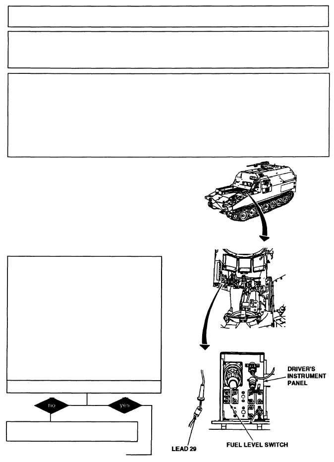
A. 1. Remove driver’s instrument panel cover
(para 7-9).
2. Disconnect harness 12330252 lead 29 from
FUEL LEVEL switch.
3. Place FUEL LEVEL switch in UPPER posi-
tion.
4. Turn MASTER switch ON (refer to TM 9-
2350-287-1O).
5. Observe fuel gage.
6. Turn MASTER switch OFF (refer to TM 9-
2350-287-1O).
Does fuel gage indicate FULL?
Replace FUEL LEVEL switch (para 7-9).
Verify problem is solved.
Continued on next page
2-121
TM 9-2350-287-20-1