TM 9-2350-287-20-1
2-19. TROUBLESHOOTING CHART (continued).
e. AIR CLEANER FAN ASSEMBLY (continued).
(1) AIR CLEANER BLOWER MOTORS DO NOT
OPERATE WITH VEHICLE IN GEAR.
lnitial Setup:
Tool/test Equipment:
•MASTER switch set to OFF (refer to
• Digital multimeter (DMM) (Item 13, Appendix I)
TM 9-2350-287-10).
• General mechanic’s tool kit
•Place vehicle in drive gear (refer to
(Item 24, Appendix I)
TM 9-2350-287-10).
Personnel Required: Two
Equipment Conditions:
•Right projectile rack moved back (refer to
TM 9-2350-287-10).
NOTE
• Instead of using multi meter
for voltage check, STE/lCE
troubleshooting, INDIVIDUAL
BATTERY VOLTAGE TEST-TEST
89 maybe performed.
• Instead of using multimeter
for continuity check, STE/lCE
troubleshooting, TEST 91 may
be performed.
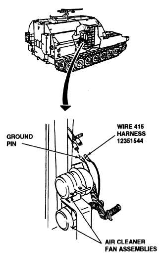
A. 1. Disconnect wire 415 of harness 12351544
from each air cleaner blower motor.
2. Disconnect ground of both air cleaner
blower motors from each socket connector.
3. Place on lead of multimeter on wire 415 pin
connector of air cleaner blower motor and
other multimeter lead on ground pin.
4. Check air cleaner blower motor for continu-
ity.
5. Repeat step3 and 4 for the other air cleaner
blower motor.
Is continuity indicated in both air cleaner blower
motors?
Replace defective air cleaner fan assembly (para
4-13). If only one air cleaner blower motor is
inoperative, continue troubleshooting at step B
after replacement. Verify problem is solved.
Continued on next page
2-81