TM 9-2350-277-34
REPAIR ROADSIDE AND CURBSIDE DATA PANEL ASSEMBLIES A12 AND A13
(M1068A3 ONLY) — Continued
0101 00
NOTE
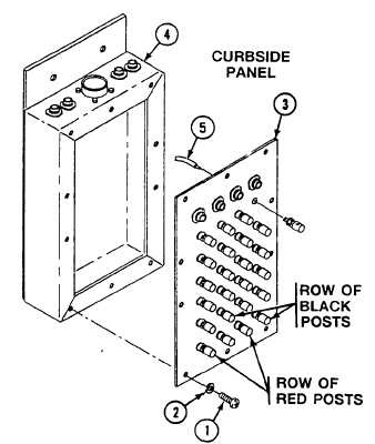
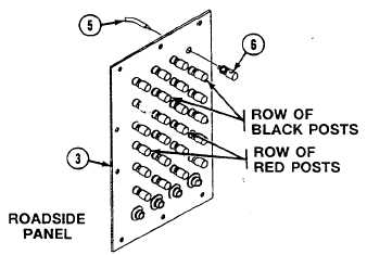
See wiring diagram page 0101 00–4 for assembly/disassembly of wires to connectors/binding
posts.
Follow illustration for assembly/disassembly of red/black binding posts.
6.
Connect leads (5) to 24 binding posts (6).
7.
Install faceplate (3) on box (4) and secure with 14 screws (1) new lockwashers (2).
0101 00-7