TM 9-2350-277-34
REPAIR ROADSIDE AND CURBSIDE DATA PANEL ASSEMBLIES A12 AND A13
(M1068A3 ONLY) — Continued
0101 00
INSTALLATION
NOTE
See wiring diagrams page 0101 00–4 for assembly/disassembly of wires to connectors/binding
posts.
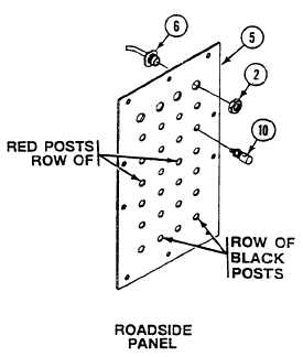
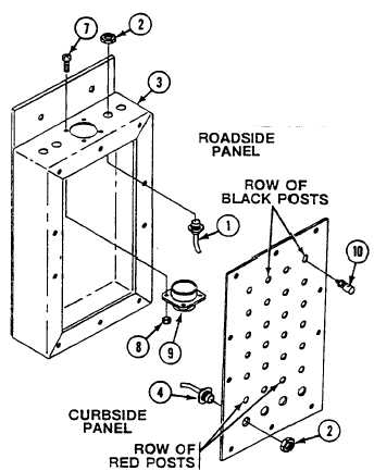
Follow illustration for assembly/disassembly of red/black binding posts.
1.
Install 24 binding posts (10) on faceplate (5).
2.
Install connector J1 (9) on box (3) and secure with four screws (7) and new locknuts (8).
NOTE
Do Step 3 for roadside data panel only. Do Step 4 for curbside data panel only.
3.
Install four connectors J109 thru J112 (6), on faceplate (5) and secure with jamnuts (2).
4.
Install four connectors J105 thru J108 (4) on faceplate (5) and secure with jamnuts (2).
5.
Install four connectors J1, J2, J4, J5 (1), on box (3) and secure with jamnuts (2).
0101 00-6