TM 9-2350-277-34
REPAIR POWER CONTROL ENCLOSURE, LEFT PANEL (M1068A3 ONLY) — Continued
0091 00
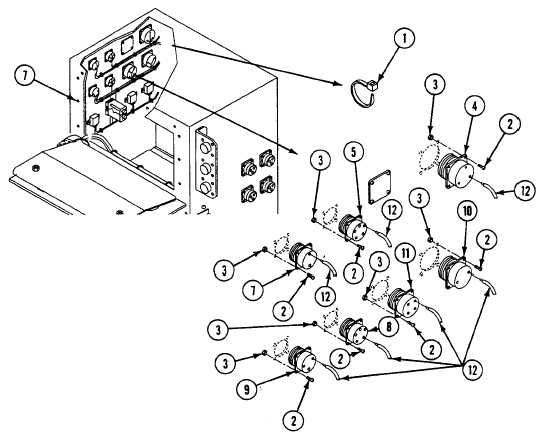
12. Remove straps (1) from wires as required. Discard straps.
13. Remove sixteen screws (2), locknuts (3), four connectors J24 (4), J31 (5), and J36 (6) from left panel (7). Discard
locknuts.
14. Remove sixteen screws (2), locknuts (3), and four connectors J30 (8), J32 (9), J33 (10), and J34 (11) from left panel (7).
Discard locknuts.
15. Remove/de-solder twenty eight wires (12) from terminals of connectors. See wiring diagram.
ASSEMBLY
1.
Solder/install twenty-eight wires (12) on terminals of connectors. See wiring diagram.
2.
Install four connectors J30 (8), J32 (9), J33 (10), and J34 (11) on left panel (7), secure with sixteen screws (2) and new
locknuts (3).
3.
Install four connectors J24 (4), J31 (5), and J36 (6) on left panel (7), secure with sixteen screws (2) and new locknuts (3).
4.
Install new straps (1) on wires as required.
0091 00-5