TM 9-2350-277-34
REPAIR/REPLACE ACCELERATOR STOP SUPPORT ASSEMBLY — Continued
0018 00
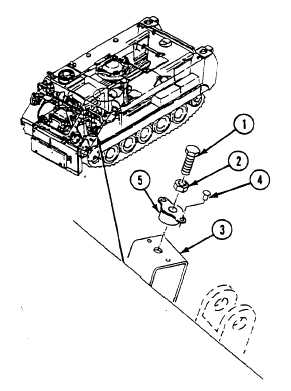
5.
Use a machinist’s hammer and a cold chisel to remove two rivets (4) securing nut (5) to support. Remove nut.
INSTALLATION
NOTE
To install nut (2) only, go directly to Step 4.
1.
Position support assembly (1) on front bulkhead 4-11/16 inches (11.9 cm) from left edge of support to engine
compartment bulkhead. Use straight edge to locate and scribe a line between mounting holes.
WARNING
Unsafe welding practices can cause serious injury from fire, explosions, or harmful agents.
Allow only authorized personnel to weld or cut metals, and follow safety precautions in TM
9-237. Protective clothing and goggles must be worn; adequate protective equipment used, a
suitable fire extinguisher kept nearby; and requirements of TM 9-237 strictly followed.
NOTE
Read (WP 0004 00) before welding.
2.
Weld support assembly (1) to floor plate, using dimensions shown, in accordance with TM 9-237. Use electrode
type 5356.
0018 00-2