TM 9-2350-277-20-6
REPLACE FLUORESCENT LIGHT ASSEMBLIES (M1068A3 ONLY)
0825 00
THIS WORK PACKAGE COVERS:
Removal (page 0825 00-1).
Installation (page 0825 00-2).
INITIAL SETUP:
Maintenance Level
Unit
Tools and Special Tools
General Mechanic’s Tool Kit (WP 0926 00, Item 65)
Personnel Required
Power-Generation Equipment Repairer 52D10
References
See your -10
TM 10-5410-229-13&P
TM 11-7010-256-12&P
Equipment Condition
Engine stopped (see your -10)
Carrier blocked (see your -10)
All external power disconnected
(TM 11-7010-256-12&P)
Battery ground lead disconnected (WP 0338 00)
REMOVAL
NOTE
For repair of fluorescent light assemblies, see TM 10-5410-229-13&P.
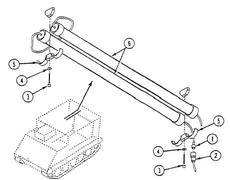
1.
Disconnect fluorescent light assembly electrical connector P1 (1) from cable W11P2 (2).
2.
Remove two thumbscrews (3), washers (4), light holders (5), and fluorescent light assemblies (6) from light holder
mounts welded to overhead plate.
0825 00-1