TM 9-2350-277-20-3
REPLACE TRANSMISSION WIRING HARNESS
0360 00
THIS WORK PACKAGE COVERS:
Removal (page 0360 00-1).
Inspection and Repair (page 0360 00-2).
Installation (page 0360 00-2).
INITIAL SETUP:
Maintenance Level
Unit
Tools and Special Tools
General Mechanic’s Tool Kit (WP 0926 00, Item 65)
Multimeter (WP 0926 00, Item 30)
Materials/Parts
Locknut ( 4 )
Personnel Required
Unit Mechanic
References
See your -10
Equipment Condition
Engine stopped (see your -10)
Carrier blocked (see your -10)
Trim vane lowered (see your -10)
Power plant access door opened (see your -10)
REMOVAL
1.
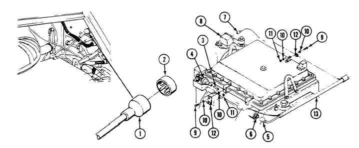
Disconnect transmission wiring harness connector (1) from bulkhead connector (2).
2.
Disconnect circuit 366 lead (3) from transmission low oil level pressure switch (4).
3.
Disconnect wiring harness connector (5) from transmission connector (6).
4.
Disconnect circuit 323 connector (7) from differential pressure switch (8).
5.
Remove four screws (9), eight washers (10), four locknuts (11), and four clamps (12) from brackets and wiring harness
(13). Discard locknuts.
6.
Remove wiring harness (13) from transmission.
0360 00-1