TM 9-2350-277-20-3
REPLACE CIRCUIT BREAKER
0280 00
THIS WORK PACKAGE COVERS:
Removal (page 0280 00-1).
Installation (page 0280 00-2).
INITIAL SETUP:
Maintenance Level
Unit
Tools and Special Tools
General Mechanic’s Tool Kit (WP 0926 00, Item 65)
Materials/Parts
Locknut (2)
Personnel Required
Unit Mechanic
References
See your -10
Equipment Condition
Engine stopped (see your -10)
Carrier blocked (see your -10)
Battery ground strap disconnected (WP 0337 00),
(WP 0338 00), or (WP 0339 00)
Instrument panel removed (WP 0295 00)
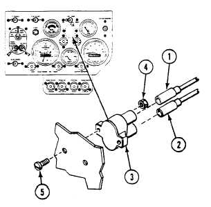
REMOVAL
1.
Disconnect circuit 10 lead (1) and circuit 27 lead (2) from circuit breaker (3).
2.
Remove two locknuts (4), screws (5), and circuit breaker (3) from rear of instrument panel. Discard locknuts.
0280 00-1