TM 9-2350-277-20-3
REPLACE INSTRUMENT PANEL ASSEMBLY — Continued
0279 00
INSTALLATION
1.
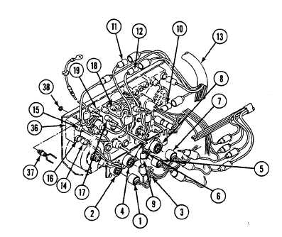
Connect lead 519/519A (1) to headlight HI beam indicator (2).
2.
Connect lead 370/27M (3) to parking brake indicator (4).
3.
Connect lead 367/27L (5) to transmission low oil pressure indicator (6).
4.
Connect lead 323/27R (7) to transmission oil clogged indicator (8).
5.
Connect lead 38 (9), lead 27P (10), lead 25A (11), and lead 27F (12) to special purpose cable (13).
6.
Connect lead 406 (14) and special purpose harness lead 27C (15) to air box heater switch (16) or glow plug switch (36).
NOTE
Skip Step 7 if your carrier has air box system.
7.
Install glow plug indicator (37) and secure with knurled nut (38).
0279 00-5