TM 9-2350-277-20-2
REPAIR DOUBLE FLEX EXHAUST JOINT
0222 00
THIS WORK PACKAGE COVERS:
Removal (page 0222 00-1).
Installation (page 0222 00-2).
INITIAL SETUP:
Maintenance Level
Unit
Tools and Special Tools
General Mechanic’s Tool Kit (WP 0926 00, Item 65)
Materials/Parts
Gasket (2)
Personnel Required
Unit Mechanic
References
See your -10
Equipment Condition
Engine stopped (see your -10)
Carrier blocked (see your -10)
Double flex joint removed (WP 0221 00)
REMOVAL
NOTE
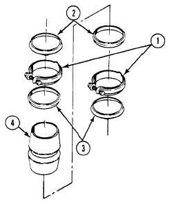
The double flex exhaust joint can be repaired by replacing the clamp, gasket, or retainer.
1.
Remove two clamps (1), gasket retainers (2), and gaskets (3) from double flex joint (4). Discard gaskets.
0222 00-1