TM 9-2350-277-20-2
REPLACE FUEL SUPPLY HOSES, TUBES, AND FITTINGS (M1064A3 ONLY)
0194 00
THIS WORK PACKAGE COVERS:
Removal (page 0194 00-1).
Installation (page 0194 00-7).
INITIAL SETUP:
Maintenance Level
Unit
Tools and Special Tools
General Mechanic’s Tool Kit (WP 0926 00, Item 65)
Materials/Parts
Calking compound (WP 0926 00, Item 65)
Sealing compound (WP 0928 00, Item 54)
Grommet
Lockwasher (6)
Personnel Required
Unit Mechanic
References
See your -10
Equipment Condition
Ramp lowered (see your -10)
Engine stopped (see your -10)
Carrier blocked (see your -10)
Power plant rear access panels removed (see your -10)
Battery ground strap disconnected (WP 0337 00)
Fuel tanks drained (WP 0177 00)
Heater duct removed (WP 0706 00)
Rear floor plates removed (WP 0543 00)
REMOVAL
1.
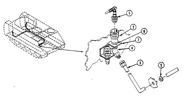
Locate quick disconnect (1) on rear bulkhead inside power plant.
2.
Separate quick disconnect nose (1) from quick disconnect body (2).
3.
Remove fuel supply hose (3) from elbow (4).
4.
Remove fuel supply hose (3) and grommet (5) from bulkhead. Discard grommet.
5.
Remove elbow (4) from coupler body (2).
6.
Remove nut (6) and coupler body (2) from bracket (7).
0194 00-1