TM 9-2350-277-20-1
INTRODUCTION TO HOW TO USE TROUBLESHOOTING—Continued
0005 00
TROUBLESHOOTING BASICS
Troubleshooting Procedure
A troubleshooting procedure serves as a starting point for your troubleshooting work. You will branch in and out of
procedures as you work to find a fault. After correcting the fault, check that the problem has been corrected. The parts of a
troubleshooting procedure are given below.
INITIAL SETUP:
Unit
T
YES
NO
TN
Y
YES
NO
YN
0019 00-1
General mechanics tool kit: automotive
(WP 0926 00, Item 65)
Multimeter (WP 0926 00, Item 30)
Tools and Special Tools
Personnel Required
Maintenance Level
TM 9-2350-277-20-1
Unit Mech 63T10
Helper (H)
References
See your -10
WAIT INDICATOR LIGHT DOESN’T LIGHT
0019 00
Equipment Condition
1. Is MASTER SWITCH ON?
1. Turn MASTER SWITCH ON.
2. Verify no faults found.
1. Replace GLOW PLUG switch
(WP 0209 00).
2. Verify no faults found.
1. Turn MASTER SWITCH OFF .
2. Remove instrument panel for access (WP 0279 00).
3. Remove circuits 406 (1) and 27C (2) plugs from GLOW PLUG
switch jacks (3) and (4).
4. Measure resistance between switch jacks (3) and (4) with GLOW
PLUG switch pressed.
5. Does multimeter read 0 ohm?
Engine stopped (see your -10)
Vehicle blocked (see your -10)
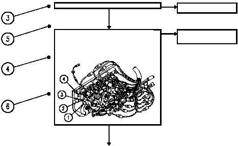
Legend to Sample Above
1 TITLE
This is the name of the procedure that best describes your symptom.
2 INITIAL SETUP
This tells you the tools, materials/parts, personnel, references, and equipment
conditions needed to do the procedure.
3 TASK STEPS
Step-by-step instructions that isolate the fault.
4 QUESTION
This is last step in YES blocks. The answer to this question will direct you to the
next block.
5 BLOCK ID CODE
These codes identify YES/NO blocks for ease of referencing. When filling out
2028s, list these codes, along with titles and page numbers.
6 ILLUSTRATIONS
These help you locate and identify parts.
0005 00-2