TM 9-2350-277-20-1
COOLANT TEMP INDICATOR MALFUNCTIONS
0053 00
INITIAL SETUP:
Maintenance Level
Unit
Tools and Special Tools
General Mechanic’s Tool Kit (WP 0926 00, Item 65)
Jumper Wire
Multimeter (WP 0926 00, Item 30)
STE/ICE Test Set (WP 0926 00, Item 61)
Personnel Required
Unit Mechanic
References
See your -10
Equipment Condition
Engine stopped (see your -10)
Carrier blocked (see your -10)
Trim vane lowered (see your -10)
Power plant access door open (see your -10)
Driver’s power plant access panel removed
(WP 0441 00)
Power plant rear access panel removed (WP 0439 00)
T
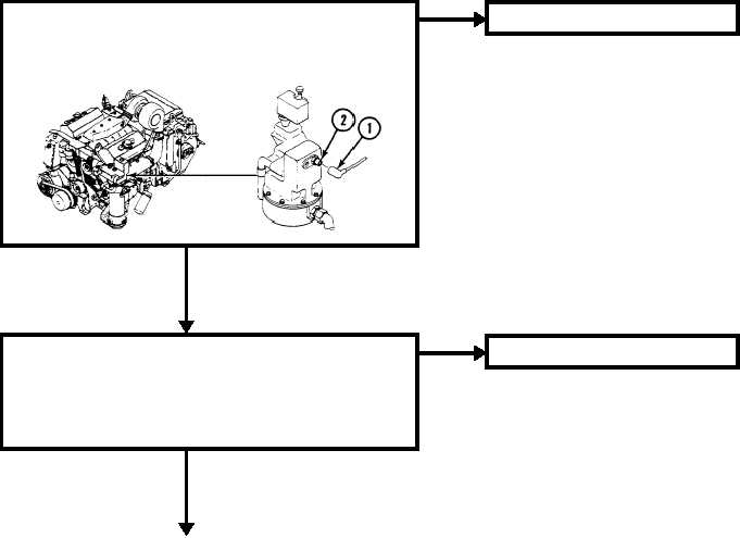
1. Remove harness 12349873 circuit 33 plug (1) from water
temperature transmitter jack (2).
2. Turn MASTER SWITCH to ON (see your -10).
3. Is TEMP indicator needle in full left (cold) position?
YES
NO
GO TO AY (PAGE 0053 00-2)
Y
1. Turn MASTER SWITCH to OFF.
2. Install jumper wire between harness 12349873 circuit 33 plug and
ground.
3. Observe TEMP indicator needle.
4. Turn MASTER SWITCH to ON for two seconds.
5. Did TEMP indicator needle move to full right (hot) position?
YES
NO
GO TO BY (PAGE 0053 00-3)
0053 00-1