6-26.2
Change 4
TM 9-2350-267-20
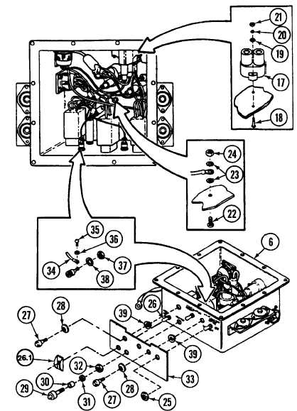
ACCESSORY CONTROL BOX: REMOVAL, DISASSEMBLY, ASSEMBLY AND INSTALLTION (CONTINUED)
C
D
E
F
G
H
I
J
NOTE
Refer to Accessory Control Box Wiring Schematic,
Appx F to ensure proper installation.
Disconnect six electrical connectors (16) from circuit breakers (17).
Remove six screws (18), six flat washers (19), six lockwashers (20), six
nuts (21) and three circuit beakers (17). Discard lockwashers.
Remove screw (22), two lockwashers (23) and nut (24). Discard lockwashers.
Unscrew three hexnuts (25) and switch guard (26.1) and pull three switches
(26) into accessory.
Remove two leads on ventilator/blower switch (26) between terminals 4
and 3, and 6 and 1.
Remove two panel light lamps (27) and two gaskets (28). Discard gaskets.
Remove indicator light cap (29), lamp (30), gasket (31), hexnut (32), and
indicator panel (33) from accessory control box (6). Discard gaskets.
Disconnect wire (34) by removing screw (35) and washer (36). Remove nut
(37) and washer (38) and pull lightbracket (39) out of aecessory control box
(6).