NOTE
Circuit breaker panel 2 is located on the sponson
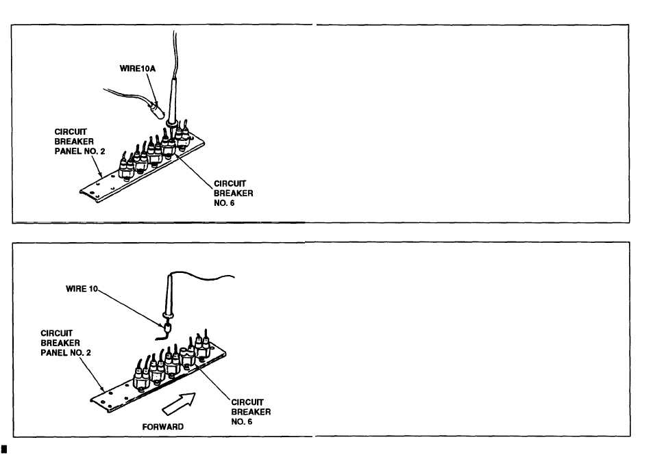
directly behind the engine T/A panel.
I Disconnect wiring harness 12351461, wire 10A from circuit breaker panel
No. 2.
J Place red lead of multimeter in circuit breaker socket and ground black lead
of multimeter.
K Check for 24 ± vdc. If voltage is indicated, repair wire 10A or replace
wiring harness 12351461 (p 14-50.5). Verify problem is solved. If no
voltage is indicated, go to step L.
L Connect wiring harness 12351461, wire 10A to circuit breaker No. 6 on
circuit breaker panel No. 2.
M Disconnect wiring harness 12351754, wire 10 from circuit breaker No. 6 on
circuit breaker panel No. 2.
N Place red lead of multimeter in wire 10 connector and ground black lead of
multimeter.
O Check for 24 ± 3 vdc. If voltage is indicated, replace circuit breaker No. 6
@6-54). Verify problem is solved. If no voltage is indicated, go to step P.
2-291
Change 4
TM 9-2350-267-20