2-146
TM 9-2350-267-20
NOTE
To trace circuits 27 and 28, check wiring harnesses
12260298 (p 6-89) and 12260287 (p 6-84).
C
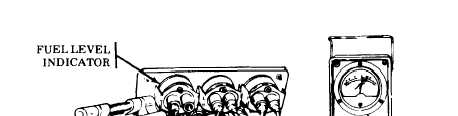
Disconnect wire 28 from FUEL LEVEL indicator. Place red
multimeter lead in wire 28, ground black lead, and check for
voltage. If voltage is present, replace FUEL LEVEL indicator
(p 6-21). If no voltage, repair or replace wires 27 and 28.
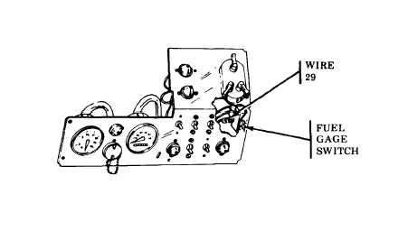
D Reconnect wire 29-31. Place FUEL GAGE switch in the UP-
PER position. Disconnect wire 29 from FUEL GAGE switch.
Turn MASTER switch ON and place FUEL GAGE switch in
UPPER position. If indicator shows a maximum reading, use
a jumper and ground FUEL GAGE switch. If indicator shows
a minimum reading, reconnect wire 29 and go to step E. If in-
dicator fails to show a minimum or maximum reading, replace
FUEL GAGE switch (p 6-19).
TA310505