2-89
UNIVERSAL JOINTS: REMOVAL AND INSTALLATION (CONTINUED)
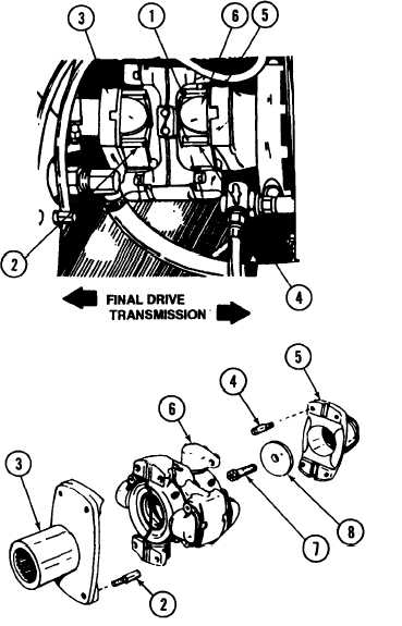
D Slide flange assembly (3) toward final drive, and adapter (5) toward
transmission. Lift out spider, plate, bumper and retainer group (6).
E
Slide flange assembly (3) off final drive.
F
Remove screw (7) and plate (8). Slide adapter (5) off transmission.
INSTALLATION
A Install plate (8) and screw (7) into adapter (5) and slide on transmission.
B
Slide flange assembly (3) on final drive.
C Hold spider, plate, bumper and retainer group (6) and mate with adapter (5)
and flange assembly (3).
CAUTION
Lock wires must be used to secure screws otherwise
serious damage can result.
D Install eight screws (2 and 4) and lock wires (1).
E Close transmission access door.
Change 4
All data on pages 2-90 and 2-91 deleted.
TM 9-2350-267-20