TRANSMISSION SHIFT CONTROL LINKAGE: ADJUSTMENT
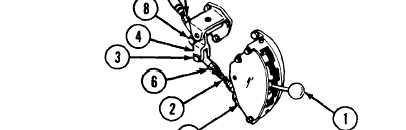
B
Place bell crank (4) parallel with lever on shift control (5). Loosen
nut (6) and adjust shift control inner rod (2) until clevis pin (3)
can be installed easily. Install flat washer and cotter pin.
Tighten nut (6).
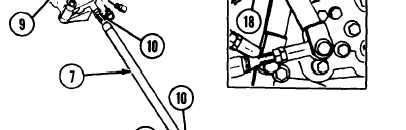
C Disconnect shift control inner tube (7) by removing cotter pin,
flat washer and clevis pin (8). With base lever (9) at neutral posi-
tion on neutral safety switch (verify by attempting to crank
engine after fuel shutoff has been pulled) and with shift lever
in neutral position, loosen nuts (10). Adjust shift control inner
tube (7) until clevis pin (8) can be easily inserted into lever of
inner bell crank (4). Install flat washer and cotter pin. Tighten
nut (10) on shift control inner tube (7).
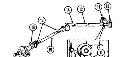
D With shift control lever (11) in neutral (N) position, check in-
dicator (18), disconnect shift control outer rod (12) from
transmission shift control lever (11) by removing cotter pin, flat
washer and clevis pin (13). Loosen nuts (14) and adjust rod to
approximately 8-1/4 inches (centerline of bearing bore to
centerline of bearing bore). Tighten nuts (14).
E
Disconnect shift control outer tube (15) by pulling quick-
disconnect pin (16). Make sure control lever (11) is in neutral
position and install shift control rod (12) in transmission shift
control lever (11). Install clevis pin, flat washer and cotter pin
(13).
F
Loosen nut (17) and adjust shift control outer tube (15) until
quick-disconnect pin (16) can be easily inserted. Tighten nuts
on shift control outer tube.
A
Place shift control lever (1) in neutral (N) position. Disconnect
G Move shift control lever (1) through all positions. In each posi-
shift control inner rod (2) by removing cotter pin, flat washer
tion, check to see that transmission shift control lever indicator
and clevis pin (3) from shift control inner bell crank (4).
(18) indicates the same as the shift control lever position.
TA310446
2-87
TM 9-2350-267-20