ELECTRICAL SYSTEM (M901A1 ONLY)
The electrical system is designed to sense pressures and temperatures, activate panel indicators, and generate
and store electrical energy.
The components and their functions are:
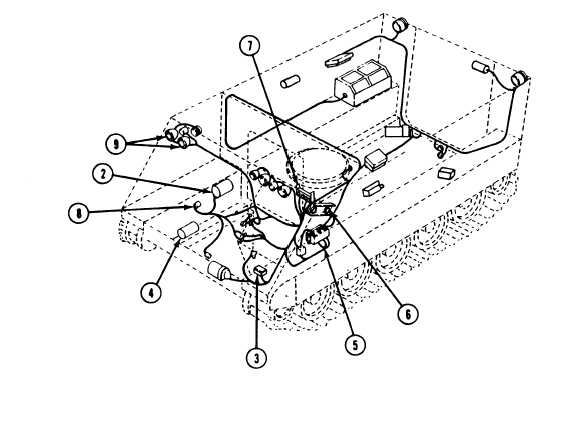
Batteries (1) store a supply of 24 V dc power.
Generator (2) supplies 24 V dc power for the system.
Regulator (3) controls voltage output of the generator.
Starter (4) cranks the engine.
Master switch panel (6) connects electrical power from the batteries to the system. Panel is
point for the main harnesses and circuit breakers. Heaters are wired direct to batteries.
Instrument panel (6) contains gages and switches necessary to control carrier.
Warning light panel (7) indicates overheating or low oil pressure in major components of
main junction
power plant.
Wiring harnesses (8) distribute power to engine, transmission, differential, and other components.
Headlights (9) are used for
night vision.
N O T E
See foldout (F04) in the rear of TM for
wiring diagram.
2-15
TM9-2350-261-20-1