TM 9-2350-261-20-1
2 0 0 A M P C H A R G I N G S Y S T E M O P E R A T I O N A L C H E CK
INITIAL SETUP
Tools :
References:
General Mechanic’s Tool Kit (Item 30, App D)
See your-10
Multimeter (Item 43, App D)
TM 9-6140-200-14
Personnel Required:
Equipment Conditions:
Unit Mechanic
Engine stopped (see your -10)
Carrier blocked (see your-10)
1. Turn MASTER SWITCH ON.
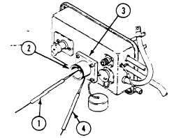
2. Measure battery voltage by placing red lead (1) in posi-
tive socket of nato plug (2) on auxiliary power (slave)
receptacle (3). Touch negative lead (4) to outside of nato
plug on receptacle.
N O TE
On carriers that have standard auxiliary
power receptacles, touch red lead to
positive and black lead to negative
sockets in the receptacle.
3. Is battery voltage more than 24.8 volts?
NO
1. Replace or charge batteries
(TM 9-6140-200-14).
2. Verify no faults found.
I
1. Start engine and run at fast idle (800 rpm) with no
I
NO
.
1. Go to no charge/regulation
troubleshooting
2. Is voltage higher than battery voltage?
(page 3-64.7).
2. Verify no faults found.
3-64.4
Change 1
electrical equipment/load.